Article Summary
Using a photoresistor with Arduino lets you detect light changes and trigger real-world responses. This article covers circuit wiring, voltage divider setup, and Arduino code for reading LDR values and controlling an LED. You'll gain the hands-on skills to build light-sensing projects confidently.
Photoresistors, also known as light dependent resistors (LDRs) or photocells, are low-cost variable resistors where the resistance changes depending on the amount of light hitting its surface. In dark environments the resistance is high; in light environments the resistance is lower. Due to the imprecise nature of photoresistors, they are unsuitable for measuring exact levels of light but are capable of detecting changes. They can be used to respond to events such as the transition from daytime to night-time (and vice versa) for home automation and gardening applications, and are often used to control street lighting. Photoresistors placed inside an enclosure can detect when it is opened or, with careful design, detect the presence of objects that block the sensor when inserted.
The code and circuits below describe the use of a photoresistor with an Arduino. Although a straightforward process, this is not an in-depth guide and beginners who are unfamiliar with that platform may wish to look at a step-by-step guide to learning the basics of the Arduino. People from an electronic engineering background might prefer a more advanced course that covers wiring, installation and programming of the Arduino and interfacing with LabView.
To complete the tutorial, you will need:
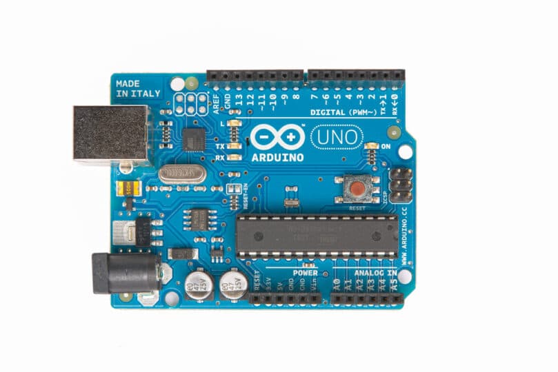
- An Arduino or Arduino-compatible board with analog inputs.
- The Arduino IDE (integrated development environment).
- A photoresistor (photocell/light dependent resistor) such as the ones from Adafruit (USA) or Maplin (UK).
- One 10Ko resistor.
- One 10Ko potentiometer (variable resistor).
- A breadboard and connecting wires (or suitable stripboard and soldering equipment).
Working with electricity, even at low voltages, can be dangerous – follow the connection diagrams and instructions carefully, and always seek advice from a qualified and experienced adult if you are unsure.
Theory of Operation
Shown below is a diagram of a breadboard circuit that you can use to begin experimenting. The photoresistor and the 10Ko resistor are powered by the Arduino’s 5V power supply and form a potential divider, which protects the Arduino from short circuits and ensures that at least some resistance is always present on the line.
A wire is connected from this circuit to analog input 0 on the Arduino. Resistors lower the voltage passing through them, and so to read changes in light from this circuit, you can use the Arduino’s analog to digital converters (ADCs) to measure the voltage level of the input. The ADCs convert the analog value to an integer in the range 0 through 1023.
When the photoresistor is exposed to light, its resistance decreases and so the voltage reading will be higher. When light is blocked, the resistance of the photoresistor increases and so the voltage reading will be lower.

The photoresistor is a simple two-terminal passive component and has no polarity – it does not matter which way round you place it in the circuit.
Programming the Arduino
To check that everything is functioning correctly, you can create a basic sketch that reads the voltage level and outputs the value to the serial port. By covering the photoresistor you will see this reading change.
To create the voltmeter sketch:
- Open the Arduino IDE.
- Paste in the following code:
/* * * Udemy.com * Using Photoresistors (LDRs) with an Arduino * */ // pin assignments int LDR = 0; // initialize the serial port // and declare inputs and outputs void setup() { pinMode(LDR, INPUT); Serial.begin(9600); } // read from the analog input connected to the LDR // and print the value to the serial port. // the delay is only to avoid sending so much data // as to make it unreadable. void loop() { int v = analogRead(LDR); Serial.println(v); delay(1000); } - Save the sketch. On the File menu, click Save As…
To upload the sketch to your Arduino and watch the output:
- Connect your Arduino to your computer with the USB cable.
- In the IDE, on the toolbar, click the Upload button.
- On the toolbar, click the Serial Monitor button.
Detecting Changes
The exact values output from the sketch above will vary depending on several factors:
- The power supply of the Arduino. Particularly when powered over a USB cable, it is common for the Arduino’s 5V power supply to be a little less than that ideal;
- The minimum and maximum resistance values of the photoresistor used;
- The accuracy of the 10Ko resistor;
- The construction of the breadboard and wires used – both of these have small levels of resistance that can affect the ADCs;
- And the amount of ambient light in the room.
It is more important to detect changes in the light level than to be concerned with the actual numbers.
The sketch below reads the light level in the setup routine, to use as a baseline measurement, and then detects when the photoresistor is obscured. When that happens, a call to digitalWrite() lights the Arduino’s built-in LED on digital pin 13.
/*
 *
 * Udemy.com
 * Using Photoresistors (LDRs) with an Arduino
 *
 */
 // pin assignments
 int LED = 13;
 int LDR = 0;
 // variables
 int base;
 int threshold = 100;
 // declare inputs and outputs
 // and take a baseline reading
 void setup() {
   pinMode(LED, OUTPUT);
   pinMode(LDR, INPUT);
   base = analogRead(LDR);
 }
 // read from the analog input connected to the LDR
 // and print the value to the serial port.
 // the delay is only to avoid sending so much data
 // as to make it unreadable.
 void loop() {
   int v = analogRead(LDR);
   if ((base - v) > threshold) {
     digitalWrite(LED, HIGH);
   } else {
     digitalWrite(LED, LOW);
   }
 }
Setting Thresholds in Hardware
The sketch above set a threshold – a value that defines how much change is expected before something happens – in the program code. Depending on your environment and application, it may be necessary to adjust that threshold. To avoid having to connect the Arduino back to the computer and reprogram it, you can use a potentiometer (“pot”) to adjust the amount of resistance in the circuit.
You can connect a pot in many ways, an example of which is shown below:

Potentiometers are another type of variable resistor – they are usually attached to a knob and their resistance is set by turning the knob left and right. In this diagram, a trim pot is used to change the voltage feeding in to the photoresistor. This affects its ability to detect light and alters the balance of the potential divider, so that the amount of change registered by the sketch (base – v, in the code above) can be increased or decreased.
For a more digital approach, you can instead wire the pot in the same way as a photoresistor and read it using a second analog input. You can then use that measurement in the sketch to determine a new value for the variable threshold.
Other Applications
The two example circuits here demonstrate the basic steps involved in detecting changes in light levels with a photoresistor and an Arduino. More interesting projects, such as for home automation and alarm systems, can be constructed using additional components like relays, motors, and wireless communication devices.
Learn more about the Arduino and useful components at Udemy.com.